In the realm of server rack infrastructure, the cage nut stands out as a pivotal innovation that has significantly influenced equipment mounting solutions. Patented on February 3, 1953, by William A. Bedford, Jr. (U.S. Patent 2,627,294), the cage nut introduced a versatile and reliable method for securing components within racks, addressing challenges associated with mounting in thin or hard-to-reach materials.
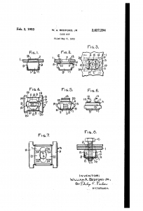
A cage nut, also known as a captive or clip nut, comprises a square nut encased within a spring steel cage. This design allows the nut to “float” slightly, accommodating minor misalignments during installation. The cage features two wings that, when compressed, enable insertion into square holes commonly found in server rack mounting rails. Upon release, the wings expand, securing the nut in place.
Versatility: Suitable for mounting equipment in racks where pre-threaded holes are absent.
Ease of Replacement: If threads become stripped, the cage nut can be easily replaced without altering the rack structure.
Material Compatibility: Ideal for use with materials too thin or soft to be tapped for threading.
Reduced Cross-Threading: The floating nature of the nut minimizes the risk of cross-threading during installation.
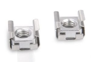
Cage nuts are available in various sizes and profiles to accommodate different equipment and rack specifications:
Standard Cage Nuts: Commonly used in general applications, compatible with standard M6, 10-32, or 12-24 screws
Low-Profile Cage Nuts: Designed for installations where space is limited, offering a smaller footprint without compromising strength.
The choice between these variants depends on the specific requirements of the equipment and the rack configuration.
Installing cage nuts requires aligning the cage with the square hole in the rack rail, compressing the wings, and inserting the assembly until it snaps into place. While installation can be performed manually, using specialized tools can facilitate the process and reduce the risk of injury or damage to the cage nut.
Beyond server racks, cage nuts are utilized in various sectors
Telecommunications: Securing equipment in network cabinets.
Automotive: Mounting components where access is limited.
Aerospace: Providing reliable fastening solutions in aircraft assemblies.
Industrial Machinery: Facilitating equipment mounting in manufacturing environments.
Their adaptability and reliability make cage nuts a preferred choice for engineers and technicians across these industries.
The invention of the cage nut by William A. Bedford, Jr. has had a lasting impact on equipment mounting solutions, particularly in the context of 19-inch server racks. Its design addresses critical challenges in installation and maintenance, offering a combination of strength, flexibility, and ease of use. As server rack configurations continue to evolve, the cage nut remains an essential component, underscoring its significance in the field of rack engineering.
For more insights into server rack components and accessories, visit www.19inchracks.co.uk.
19-inch Racks – market drivers for Growth ?
In the world of IT, audio-visual, and industrial installations, 19-inch cabinets are the backbone for housing crucial equipment. Ensuring these cabinets are correctly earthed (grounded) is not just best practice – it’s a fundamental safety requirement in the UK, protecting both your valuable equipment and, most importantly, personnel.
This blog post will guide you through the essential steps for safely earthing your 19-inch cabinets in accordance with UK regulations. Remember, if you are unsure or uncomfortable with any aspect of electrical work, always consult a qualified electrician.
Why is Earthing Crucial?
Earthing provides a safe path for fault currents to flow to earth in the event of an electrical fault. Without proper earthing, these fault currents could:
UK Regulations and Standards
Earthing practices in the UK are governed by the IET Wiring Regulations (BS 7671). While this post provides general guidance, always refer to the latest edition of BS 7671 and any specific site requirements. Key principles include:
Steps to Earth Your 19-Inch Cabinet:
Here’s a step-by-step guide to earthing your 19-inch cabinet in the UK:
1. Identify the Earthing Point on the Cabinet:
Most 19-inch cabinets will have a dedicated earthing point. This is typically:
2. Gather the Necessary Materials:
You will need the following:
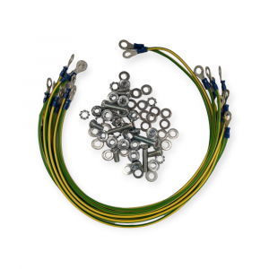
3. Connect the Earth Cable to the Cabinet:
4. Connect the Other End of the Earth Cable to the Building’s Earth Terminal:

5. Verify Earth Continuity:
This is a crucial step to ensure the earthing is effective. Use a multimeter with a continuity test function:
Important Considerations:
Conclusion:
Properly earthing your 19-inch cabinets in the UK is a vital safety measure. By following these steps and adhering to the IET Wiring Regulations, you can ensure the safety of your equipment and personnel. Remember, when in doubt, always consult a qualified electrician. Stay safe and keep your ground control secure!
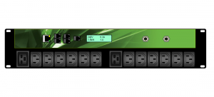 Intelligent Power Management: Exploring the Benefits of Smart PDUs
In the digital age, technology is evolving rapidly. One such development is in power management. Specifically, we see advancements in data centres and networking environments. The Intelligent Power Distribution Unit (PDU) is critical to this evolution. This post discusses its benefits and implications for network managers.
Intelligent PDUs are network-connected devices. They offer power to other connected devices. They have capabilities beyond traditional PDUs. This includes comprehensive power management features. They also provide remote monitoring and control. Additionally, they offer environmental monitoring, power metering, and load balancing.
Intelligent PDUs offer remote power monitoring in real-time. This allows network managers to track each device’s energy consumption. They can identify overused and underused equipment. These PDUs give detailed visibility of energy usage. Therefore, you can optimize energy usage and reduce wastage. Consequently, overall data centre efficiency is increased.
Intelligent PDUs provide advanced alerting capabilities. They warn network managers of potential power issues. This happens before system failure occurs. Network managers can therefore act proactively. This improves network reliability and uptime.
Intelligent PDUs provide power metering and load balancing. These features offer in-depth insights into power usage. Network managers can understand power utilization trends. They can also forecast future needs. Capacity planning becomes more manageable. This data is crucial in making informed decisions. This includes decisions on hardware upgrades and data centre expansion.
Smart PDUs offer remote control features. Network managers can control power to individual outlets. They can also manage groups of outlets. This can be done from anywhere, at any time. This provides flexibility and reduces the need for onsite visits.
Smart PDUs are a strategic tool for network management. They give managers more control and information.
In summary, intelligent PDUs are sophisticated devices. They offer crucial data and control capabilities. Network managers can use them to improve network performance and efficiency. Thus, incorporating them into your infrastructure is a smart move. They ensure power management is advanced and efficient.
When planning your next IT or telecom installation, choosing the right rack standard is critical. While both 19-inch racks and ETSI racks are commonly used in infrastructure builds, they differ significantly in dimensions, design, and application. In this article, we’ll explore the key differences between a 19-inch rack and an ETSI rack to help you select the best option for your project.
The most obvious difference lies in their width:
19-Inch Rack: Measures 482.6 mm (19 inches) between the vertical mounting rails. This has become the global standard for IT, networking, and AV gear.
ETSI Rack: Measures 535 mm between the rails and was specifically developed to accommodate larger telecom equipment typically used in Europe.
While the 19-inch rack is more compact, the ETSI rack provides extra internal space, which is ideal for wide telecom hardware and cable routing.
19-Inch Rack Origin: USA
Initially developed in the early 20th century, the 19-inch rack standard became the de facto format for computing, networking, and AV industries worldwide.
ETSI Rack Origin: Europe
Designed by the European Telecommunications Standards Institute (ETSI), this rack type is favored across European telecom sectors due to its tailored support for telecom modules and frames.
| Rack Type | Primary Use |
|---|---|
| 19-Inch Rack | Data centres, servers, AV gear, IT |
| ETSI Rack | Telecom switching & transmission |
The 19-inch rack is preferred for general IT environments, thanks to its compatibility with a broad ecosystem of servers, switches, patch panels, and power systems. On the other hand, ETSI racks dominate telecom networks, where equipment such as DSLAMs, multiplexers, and telephony gear require specific mounting options.
Because of its popularity, the 19-inch rack benefits from a vast global marketplace of compatible accessories, including:
Cable management trays
Power Distribution Units (PDUs)
Shelves
Blanking panels
Airflow management tools
ETSI racks, in contrast, rely on telecom-specific accessories that are not always interchangeable with 19-inch counterparts.
19-Inch Racks: Commonly range from 600 mm to 1200 mm in depth. These deeper racks support high-density server setups with front-to-rear airflow and cooling integration.
ETSI Racks: Often shallower (300 mm to 600 mm), suitable for wall-mounted or compact telecom spaces. They typically feature front-only mounting and less complex cooling requirements.
Another core difference is the rail configuration:
19-Inch Rack: Typically has front and rear mounting rails, providing stability for heavier equipment and more flexible cable routing.
ETSI Rack: Generally features front-only mounting, designed for lightweight and front-access telecom gear.
If you’re building or expanding a data centre, IT room, or AV setup, a 19-inch rack is likely the best fit. It’s universally supported, scalable, and adaptable to nearly any technology application.
However, if you are installing systems for a telecommunications provider or ISP in Europe, the ETSI rack offers a more specialised solution tailored to those industry standards.
Understanding the key differences between a 19-inch rack and ETSI rack ensures your infrastructure is efficient, compliant, and future-ready. At 19 Inch Racks, we offer a wide selection of both rack types, including bespoke options tailored to your project needs.
Ready to build smarter? Browse our racks and accessories or get in touch with our team to discuss your setup today.
Pros:
Cons:
Pros:
Cons:
If you need to move the rack frequently, then castors are the best option. However, make sure to choose castors that are rated for the weight of your rack and equipment. You should also take steps to prevent the rack from tipping over, such as anchoring it to the floor or wall.
If the rack is stationary and not moved frequently, then screw jack feet are the best option. They provide greater stability and allow you to level the rack on uneven surfaces.
Here are some additional factors to consider when choosing between castors and screw jack feet:
There are a multitude of different plug types available for PDU (Power Distribution Unit) power connections. Below is an overview of the most commonly used types in data centres, server rooms, and industrial applications.
This 3-pin plug is commonly used for computer and server power supplies. It has a rated current of up to 10 amps and is often referred to as a “kettle plug” due to its similar appearance.
The C20 is a 3-pin plug designed for high-power applications, such as server racks and industrial-grade equipment. It supports a rated current of up to 16 amps and is a step up from the C14 in power handling.
This plug is widely used in UK industrial applications and supports a rated current of up to 16 amps. It is often paired with 3-phase power supplies and known for its robust design suitable for harsh environments.
Also used in industrial environments, this 3-pin plug handles up to 32 amps and is ideal for powering high-power equipment. Like its 16A counterpart, it is commonly associated with 3-phase power systems.
This is a global standard for appliance couplers used in AC electrical systems. Common plug types in this category include:
This standard covers industrial and multiphase plugs and socket outlets, typically found in demanding environments. The 16A and 32A Commando plugs fall under this specification and are built for high-durability and power-heavy use cases.
